-

Dear Jack,
From my experience, elk geometry optimization is very tricky.
I see that your P3_121 cell vectors have length of 5.65, 5.65, 4.77 Angstrom, while here they are 4.51, 4.51, 5.96 A. Yours seem to be way off.First things to check here are:
1. Muffin-tin radii. Make sure they do not change: compare radii in Te.in and INFO.OUT. Changing RMTs result in changing basis, making geometry optimization weird. I'd say you need at least 10% of bond length between the MTs (i.e. RMT = 0.45 x R(Te-Te)).
2. Check your k-point grid: try task 0 with autokpt = t and radkpt = 60.
3. Add vkloff option:vkloff 0.25 0.125 0.625
- I do not like highq/vhighq options because they hide the important parameters, and remove the possibility to test which parameter in particular it the most crucial for quality improvement - but that is just me. I'd start with just increasing rgkmax. Check INFO.OUT for "Maximum |G+k| for APW functions" - I sense it must be at least 3.8-4.0 in this case.
- With all that, make sure your settings result in a smooth EOS. For that, use task 0 and change the scale. Note that scale steps must be small, i.e. 0.985, 0.986, 0.987... 1.012, 1.013. 1.014, 1.015.
- With smooth EOS, it is safe to try geometry optimization. Still, I'd start with latvopt=0, and check it the resulting geometry is fine.
Finally, it would be nice if you post the whole inputs here, elk.in with initial geometry and Te.in.
Good luck!
Andrew.
-

Hi Andrew, thanks very much for your thoughts.
The species files used were the defaults. I’m not getting a message that elk has changed the muffin tin radius, so I assume it’s being left at the default value.
As mentioned, the lattice vectors and atomic positions in my intial post were not the starting structures, but rather where the ELK geometry optimisation has currently gotten to. The starting structure for the P3_121 structure was taken from the output of the CASTEP geometry optimisation:
and is in fact nearly identical to the structure from the materials database you posted. If you put this into ELK, at least with the settings used in my first post, you end up with the structure I posted after many geometry optimisations (which, interestingly, has C2 symmetry not P3_121 symmetry).
I too do not like presets such as the
highqandvhighqoptions and would not normally use these with any code, I just wanted to dive right in and get a rough relaxation. Anyhow, I’ve now done full convergence testing (see attached). The system converges rather quickly with respect to kpoint grid dimensions (I’m using 12x12x12 with no offset), and requires an rgkmax of around 9 or so (which coincidentally is what thevhighqoption was using). My current elk.in file (for the P3_121 structure) is:tasks 2 latvopt 1 xctype 20 nrmtscf 2.0 epsengy 1e-5 msmooth ! smoothing for V_xc 4 lmaxapw 10 lmaxo 8 autolinengy .true. deltast ! size of change in lattice vectors used to compute stress tensor (reduced slightly from default) 8e-4 ngridk 12 12 12 rgkmax ! default is 7.0 9 gmaxvr ! default is 12.0 25 tempk ! FD smearing temperature (Kelvin) 300 epspot ! a bit stricter than the default (1e-6) for more accurate forces 1.e-7 epsstress ! stress convergence tolerance (default is way too strict) 1.e-3 mixtype 3 maxlatvstp 500 avec 4.2628729 -7.3837025 -0.0000248 4.2628729 7.3837025 0.0000248 -0.0000000 0.0000380 11.2476779 sppath './' atoms 1 : nspecies 'Te.in' : spfname 3 : natoms; atposl below 0.268302000 -0.000101000 0.333382000 -0.000101000 0.268302000 0.666618000 0.731799000 0.731799000 0.000000000
I’ve started this geometry optimisation from scratch, we’ll see how it goes.
Last edit: Jack Whaley-Baldwin 2020-05-15


-


-
Dear Jack,
This is a fine input, although gmaxvr 25 seems to be quite a lot.
I'd use 15 and no msmooth.
Worth trying lradstp = 2 or 1 (even more points for MT grid).
I'd try EOS next.Best regards.
Andrew
-
Hi Andrew,
Attached is the EOS plot for P3_121 tellurium. Looks pretty good.
I'm going to give the geometry optimisation another shot from scratch using:
tasks
  2

latvopt
  1

xctype
  20

nrmtscf
  2.0

epsengy
  1e-5

lmaxapw
  10

lmaxo
  8

lradstp
  2

autolinengy
  .true.

deltast ! size of change in lattice vectors used to compute stress tensor (reduced slightly from default)
  8e-4

ngridk
  12 12 12

rgkmax ! default is 7.0
  9

gmaxvr ! default is 12.0
  16

tempk ! FD smearing temperature (Kelvin)
  300

epspot ! a bit stricter than the default (1e-6) for more accurate forces
  1.e-7

epsstress ! stress convergence tolerance (default is way too strict)
  1.e-3

mixtype
  3

maxlatvstp
  500

avec
  4.2628729  -7.3837025  -0.0000248
  4.2628729   7.3837025   0.0000248
 -0.0000000   0.0000380  11.2476779

sppath
  './'

atoms
  1                                    : nspecies
  'Te.in'                              : spfname
  3                                    : natoms; atposl below
  0.268302000 -0.000101000  0.333382000
 -0.000101000  0.268302000  0.666618000
  0.731799000  0.731799000  0.000000000
Furthermore: Is the procedure of taking the last geometry in GEOMETRY_OPT.OUT and inserting this into elk.in (with task=3) the preferred way of continuing geometry optimisations in ELK?
Jack
Last edit: Jack Whaley-Baldwin 2020-05-16
-

-

Dear Jack,
I do not know what you want to do, but if you want to optimize the structure within the P3_1 21 symmetry you need to give a structure that do belong to the space group. Your data is slightly deviating.
But
avec
a -asqrt(3) 0.0
a +asqrt(3) 0.0
0.0 0.0 cwould fullfill the criteria together with
atoms
1 : nspecies
'Te.in' : spfname
3 : natoms; atposl below
x 0.0 0.333333333
0.0 x 0.6666666666
-x -x 0.0where in you case you can start with
a=4.2629
c=11.2477
x=0.2683This set up will stay within the space group by construction.
Good luck!
Bes wishes,
Lars
-
Hi Lars,
I'm not particularly concerned about keeping the P3_121 symmetry. In fact, from previous experience, use of symmetry in geometry optimisations can prevent the optimiser from distorting into a lower symmetry if it wants to, and such distortions can sometimes lower the energy. Further, it seems to me that an experimentalist has determined the structure has P3_121 symmetry only up to some tolerance, and therefore it seems wrong to a-priori force the structure to always have this symmetry, and we need to allow it to relax into a lower symmetry structure if it wants to (of course, it may end up keeping the P3_121 symmetry).
Many codes allow the user to explicitly turn symmetry off, so that kpoints are now treated inequivalently; the advantage being that lower symmetry distortions can now take place, the disadvantage being the obvious increase in computational time.
-
Dear Jack,
you do want you want.
However, I would first optimize the structure within the space group and then perhaps switch off the symmery and increase the accuracy to check if it stays there. Alternatives require high accuracy and large amount of computer time, to be certain that one stay on an accurate Born-Oppenheimer surface and do not stray off ...
/Lars
-
Hi again Jack,
Just comments to your statements, to be clear:
1) In fact, from previous experience, use of symmetry in geometry optimisations can prevent the optimiser from distorting into a lower symmetry if it wants to, and such distortions can sometimes lower the energy.
That is not just from "previous experience" -- it is an obvious fact. If you enforce a symmetry you wil not allow any symmetry breaking. But structures far from equilbrium might have instabilities although the stable symmetric one has not, which will bring you on to a very expensive detour ...
2) Many codes allow the user to explicitly turn symmetry off, so that kpoints are now treated inequivalently; the advantage being that lower symmetry distortions can now take place, the disadvantage being the obvious increase in computational time.
I am sure all codes allow a switching off of the symmetry, at least elk does that. However what you do is something else ... But I believe the distortions you see in CASTEP is just numerical noise, right? Or do you actually think that they are due to symmetry breaking?
With this I leave you to do whatever yo want to do ...
/Lars
-
Hi Lars,
By 'previous experience' I meant that I have encountered examples where turning symmetry off actually gives rise to a structure with a different (lower symmetry) space group with a genuinely lower energy - definitely not 'numerical noise'. It is indeed an obvious fact.
A good example of this is in sulfur, where geometry optimising the high-pressure C2/m phase with symmetry turned on gives a structure with C2/m symmetry. Turning symmetry off and repeating, the structure relaxes into a triclinic P-1 phase, lower in energy by around 5meV or so (with both PBE and LDA). The atomic positions change by around 0.1 Angstrom or so in this distortion; definitely above what could be considered numerical noise.
I concede that in this P3_121 case, such a distortion may indeed not occur. However, notwithstanding the increased computational expense, it is safer IMO to not use symmetry for a first optimisation. Of course, should the structure retain the symmetry and not distort, then one could safely turn it back on.
Having said all that, the optimisation is progressing very slowly once again, so perhaps I'll have a go at constraining the space group.
Jack
-
As per Lars' suggestion, I have satisfied the P3_121 symmetries to an even higher precision in the input file, and ELK now detects all six symmetry operations associated with the P3_121 group.
I am running the geometry optimisation with the following elk.in file:
tasks
  2

latvopt
  1

xctype
  20

nrmtscf
  1.5

epsengy
  1e-5

lmaxapw
  9

lmaxo
  8

lradstp
  2

autolinengy
  .true.

deltast ! size of change in lattice vectors used to compute stress tensor (reduced slightly from default)
  8e-4

ngridk
  12 12 12

rgkmax ! default is 7.0
  9

gmaxvr ! default is 12.0
  16

tempk ! FD smearing temperature (Kelvin)
  300

epspot ! a bit stricter than the default (1e-6) for more accurate forces
  1.e-7

epsstress ! stress convergence tolerance (default is way too strict)
  1.e-3

mixtype
  3

maxlatvstp
  500

avec
  4.2382128  -7.3407999  -0.0000000
  4.2382128   7.3407999  -0.0000000
  0.0000000   0.0000000  11.2585250

sppath
  ‘./‘

atoms
  1                                    : nspecies
  'Te.in'                              : spfname
  3                                    : natoms; atposl below
  0.273902304  0.000000000  0.333333000
  0.000000000  0.273902304  0.666666333
  0.726097696  0.726097696  0.999999667
Sadly, the optimisation is progressing even worse than before, with the STRESSMAX.OUT just monotonically increasing at each step:
  0.7705755252E-01
  0.7672815173E-01
  0.7820313840E-01
  0.7391438885E-01
  0.8564119980E-01
  0.1047016258
  0.1513806546
  0.2316361315
  0.3926069166
The results of FORCEMAX.OUT appear to oscillate about 4E-3:
  0.2011089225E-02
  0.2117301027E-02
  0.2736478942E-02
  0.3934264540E-02
  0.5629145754E-02
  0.5577280565E-02
  0.5365321910E-02
  0.5044752052E-02
  0.4618201954E-02
  0.6548372504E-02
  0.5864986248E-02
  0.4925214806E-02
  0.7572132353E-02
  0.6246429185E-02
  0.4489084498E-02
  0.8895459063E-02
  0.6481082171E-02
  0.3251611896E-02
  0.1162558613E-01
  0.7063260108E-02
  0.6444612522E-03
  0.1710294853E-01
  0.7833525404E-02
  0.5788422092E-02
  0.5853277879E-02
TOTENERGY.OUT:
    -20390.9048726
    -20390.9030956
    -20390.8871350
    -20390.8695341
    -20390.8578511
    -20390.8532682
    -20390.8517761
    -20390.8518963
    -20390.8520802
    -20390.8520891
-

Dear All,
The problem is that the energy differences required for calculating the stress tensor are very small and reaching the limit of numerical accuracy.
This is particularly problematic with GGA because of the large gradients of the density near the nucleus. On top of this, you are actually pretty close to equilibrium.
Nevertheless there are a couple of tricks to overcome this. The first is to increase the strain tensor step size, and the second is to give the nucleus a finite radius.
Here is my input file:
tasks
  2

deltast
  0.005

latvopt
  1

atpopt
  0

vhighq
 .true.

ngridk
  8  8  8

ptnucl
 .false.

xctype
  20

maxlatvstp
  100

avec
   7.254623976      -4.248691010      0.1104921371
   7.254623976       4.248691010      0.1104921371
 -0.6325027594E-01   0.000000000       10.76686969

atoms
  1                                    : nspecies
  'Te.in'                              : spfname
  3                                    : natoms; atposl below
    0.00000000    0.00000000    0.00000000
    0.31968171    0.31968171    0.33401274
   -0.31968171   -0.31968171   -0.33401274
Note that 'deltast' has been set to 0.005 (I've now made this the default in the code) which makes the finite energy differences larger.
The variable 'ptnucl' has been set to .false. which changes the nucleus from a point particle to a charged sphere with the estimated physical radius of the nuclei. The effect of this is to make the density gradients near the origin less extreme. Note that this has a dramatic effect on the total energy.
I've also switched off atomic position optimisation with 'atpopt' = 0, to focus on lattice optimisation alone.
Here is the energy vs. optimisation step data:
-20419.8265521
-20419.8265522
-20419.8265525
-20419.8265530
-20419.8265542
-20419.8265557
-20419.8265566
-20419.8265582
-20419.8265599
-20419.8265614
-20419.8265629
-20419.8265647
-20419.8265659
-20419.8265675
-20419.8265687
-20419.8265692
-20419.8265694
-20419.8265700
-20419.8265708
-20419.8265719
-20419.8265727
-20419.8265737
-20419.8265742
-20419.8265755
-20419.8265763
-20419.8265778
-20419.8265795
-20419.8265812
-20419.8265817
-20419.8265835
-20419.8265842
-20419.8265844
-20419.8265844
-20419.8265844
-20419.8265858
-20419.8265874
-20419.8265903
-20419.8265936
-20419.8265957
-20419.8265965
-20419.8265964
-20419.8265950
-20419.8265943
-20419.8265946
-20419.8265967
-20419.8265979
-20419.8265993
-20419.8266021
-20419.8266041
-20419.8266059
-20419.8266051
-20419.8266035
-20419.8266028
-20419.8266014
-20419.8266000
-20419.8265996
-20419.8266006
-20419.8266007
-20419.8266006
-20419.8266020
-20419.8266025
-20419.8266029
-20419.8266036
-20419.8266043
-20419.8266038
-20419.8266045
-20419.8266052
-20419.8266067
-20419.8266083
-20419.8266094
-20419.8266108
-20419.8266118
-20419.8266117
-20419.8266115
Which is relatively smooth and mostly decreasing.
The final lattice vectors are:
 avec
   7.215231666      -4.193817794      0.7027906994E-01
   7.215231666       4.193817794      0.7027906994E-01
 -0.1350686067       0.000000000       10.95587791
Another way of optimising the structure which avoids these numerical difficulties is to calculate several points of the total energy vs. each lattice vector or atomic position in turn, and fit the curve to a parabola. This is obviously quite cumbersome but sometimes more reliable than direct optimisation.
Regards,
Kay.
-
Many thanks for your input John, I'll give it a try.
Jack
-
Hi Kay,
I incorporated your suggestions of
deltast 0.005,ptnucl .false.andatpopt 0into my run, giving an elk.in file of:atpopt ! just optimise lattice vectors for this run 0 ptnucl .false. maxlatvstp 100 epsengy 1e-5 lorbcnd .true. trimvg .true. lmaxapw 10 lmaxo 10 lradstp 2 autolinengy .true. ngridk 30 30 30 rgkmax ! default is 7.0 10 gmaxvr ! default is 12.0 18 tempk ! FD smearing temperature (Kelvin) 300 epspot ! a bit stricter than the default (1e-6) 1.e-7 epsstress ! stress convergence tolerance (default is way too strict) 1.e-3 mixtype 3 avec 4.2636082 -7.3847860 0.0000000 4.2636082 7.3847860 0.0000000 0.0000000 0.0000000 11.2457997 sppath './' atoms 1 : nspecies 'Te.in' : spfname 3 : natoms; atposl below -0.268334780 -0.268334780 0.000000000 0.268334780 0.000000000 0.333333333 0.000000000 0.268334780 0.666666666
Sadly however, the STRESSMAX.OUT increases at every iteration:
  0.8229641462E-01
  0.8250245883E-01
  0.8372714728E-01
  0.8618554057E-01
  0.9005019892E-01
  0.9547752779E-01
  0.1021460128
  0.1106696145
  0.1209038513
  0.1328831648
  0.1566493542
  0.1896359092
  0.2287045143
  0.2684532490
(the run timed out, so there are only so many iterations).
Last edit: Jack Whaley-Baldwin 2020-06-05-
-
Hi Jack,
Did you post the correct input file above? None of the new options are in it.
Here is my STRESSMAX.OUT:
  0.3756817023E-03
  0.3206456313E-03
  0.3860011930E-03
  0.3354587534E-03
  0.2637352736E-03
  0.3041517630E-03
  0.2837914508E-03
  0.2619126462E-03
  0.2039712854E-03
  0.2124725142E-03
  0.2426546416E-03
  0.2529472113E-03
  0.2604581823E-03
  0.2658671292E-03
  0.2477332600E-03
  0.3022360033E-03
  0.3087443474E-03
  0.3059249138E-03
  0.2910062904E-03
  0.2854212653E-03
  0.2729342668E-03
  0.3280714736E-03
  0.2869150194E-03
  0.2931956260E-03
  0.2671651600E-03
  0.2304390364E-03
  0.2497159585E-03
  0.2939079423E-03
  0.3028188075E-03
  0.2913868229E-03
  0.3221357474E-03
  0.2997730917E-03
  0.2756234608E-03
  0.2624663466E-03
  0.2362983651E-03
  0.2609223884E-03
  0.2151595254E-03
  0.2555745596E-03
  0.2562788723E-03
  0.3714609193E-03
  0.3016575647E-03
  0.2717286407E-03
  0.2553606464E-03
  0.2350752766E-03
  0.2010798198E-03
  0.2013584890E-03
  0.1731503289E-03
  0.2156768460E-03
  0.1982101821E-03
  0.2435539500E-03
  0.2621338353E-03
  0.2156761184E-03
  0.1981257810E-03
  0.1529660949E-03
  0.1770036761E-03
  0.1864944352E-03
  0.1551677997E-03
  0.1716674888E-03
  0.2126966137E-03
  0.1695509127E-03
  0.1388514647E-03
  0.2552886144E-03
  0.1087901182E-03
  0.1007196261E-03
  0.2056171070E-03
  0.1903790690E-03
  0.2507775207E-03
  0.2040425898E-03
  0.1618223905E-03
  0.9465657058E-04
  0.6635964382E-04
  0.9099458111E-04
  0.1486478141E-03
  0.1035718014E-03
The values are about two orders of magnitude less than yours.
Regards,
Kay.
![]()
Hi Kay,
Sorry, I had indeed posted the wrong files from a different run. I have now updated the post.
As you can see however, the stress still rises at every iteration.
![]()
I usually work with plane-wave pseudopotential codes (namely CASTEP), and I'm trying to find the energy difference between two Tellurium structures at 0GPa with PBE, and compare my results to an all-electron code (ELK).
The two structures, P3_121 and C2/m Tellurium, are both three-atom cells and are not particularly complex systems. The P3_121 structure is the known ground state of Tellurium at 0GPa. The geometry optimisation in CASTEP progressed fairly quickly, even with very expensive parameters required for a highly converged calculation.
This is my elk.in file (minus the avec and atomic positions sections), common to both runs:
tasks
  3

latvopt
  1

! very high-quality calculation for precise total energies
vhighq
 .true.

! speed the calculation up with Broyden mixing
mixtype
  3

sppath
  './'

xctype
  20

maxlatvstp
  500
Where I'm using task=3, and when my job times out, feeding the last iteration of GEOMETRY_OPT.OUT into the elk.in file (when the job doesn't finish cleanly (i.e. is timed-out), the last entry in GEOMETRY.OUT does not correspond to the very-latest geometry, so I've been using GEOMETRY_OPT.OUT; the differences however should be small).
The C2/m structure is currently (this is after a few geometry optimisation runs in ELK, so not exactly the same as my initial geometry):
avec
   7.254623976      -4.248691010      0.1104921371
   7.254623976       4.248691010      0.1104921371
 -0.6325027594E-01   0.000000000       10.76686969

 atoms
  1                                    : nspecies
  'Te.in'                              : spfname
  3                                    : natoms; atposl below
    0.00000000    0.00000000    0.00000000
    0.31968171    0.31968171    0.33401274
   -0.31968171   -0.31968171   -0.33401274
The P3_121 structure is currently (again, this is after a few geometry optimisation runs, so changed a bit from the initial geometry):
avec
   4.197138605      -9.701302274       1.501966572
   4.201771084       9.701532868      -1.500547221
 -0.9702235964E-03   5.651641513       7.022420779

 atoms
  1                                    : nspecies
  'Te.in'                              : spfname
  3                                    : natoms; atposl below
   -0.00026408    0.00036656   -0.00076124
    0.72980065    0.26742565    0.99872127
    0.35448846    0.62101399    0.49665019
If you calculate the symmetry of the above structure, you'll actually see that ELK has actually pushed it into a C2 symmetry. Interestingly, this did not occur when optimising in CASTEP (and the CASTEP run was not symmetry-constrained, i.e. it too could have fallen into a lower symmetry if it wanted to).
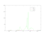
Anyhow, my concern is that after several days of optimisation, the STRESSMAX for the C2/m structure seems to be oscillating around 3E-3 and not getting any smaller, and for the P3_121 structure oscillating around 2E-2, again not getting any smaller. I have attached a plot of the STRESSMAX.OUT file for the C2/m structure; the P3_121 result is visually similar, just greater by a factor of 10 or so.
The FORCEMAX.OUT file for both structures is not bad; the last entry for the C2/m case is 6E-6, and for the P3_121 case is 2E-4.
https://sourceforge.net/p/elk/discussion/897820/thread/70a9946f87/


0 Comments